Emergency Comm HF Station
Portable Amateur Radio Two-way Station (PARTS)
Portable Amateur Radio Two-way Station (PARTS) for portable field operations
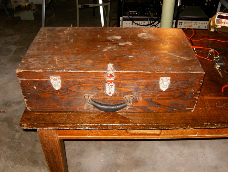
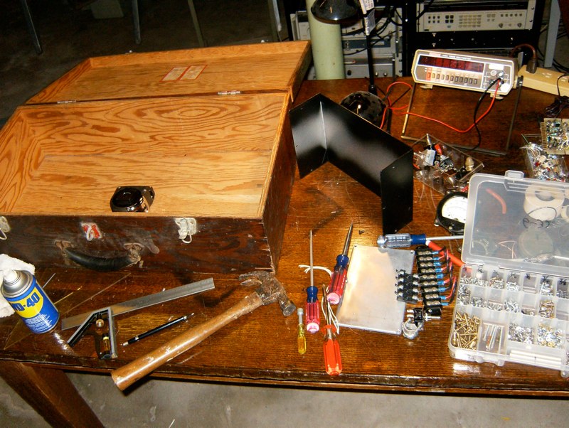
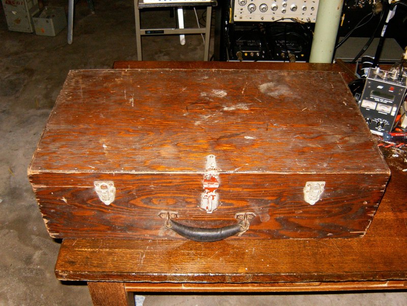
- Complete two-way HF radio station built into a WW2 foot locker
- Compact design allows for easily deployable amateur radio use in the field
- Allows for easily deployable use in a rental house or apartment where space is cramped
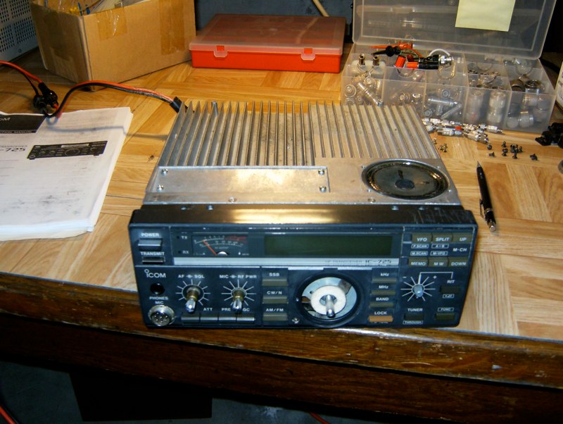
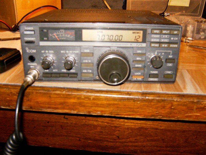
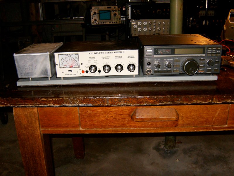
- Icom IC-725 HF transceiver, 100 watts
- MFJ antenna tuner
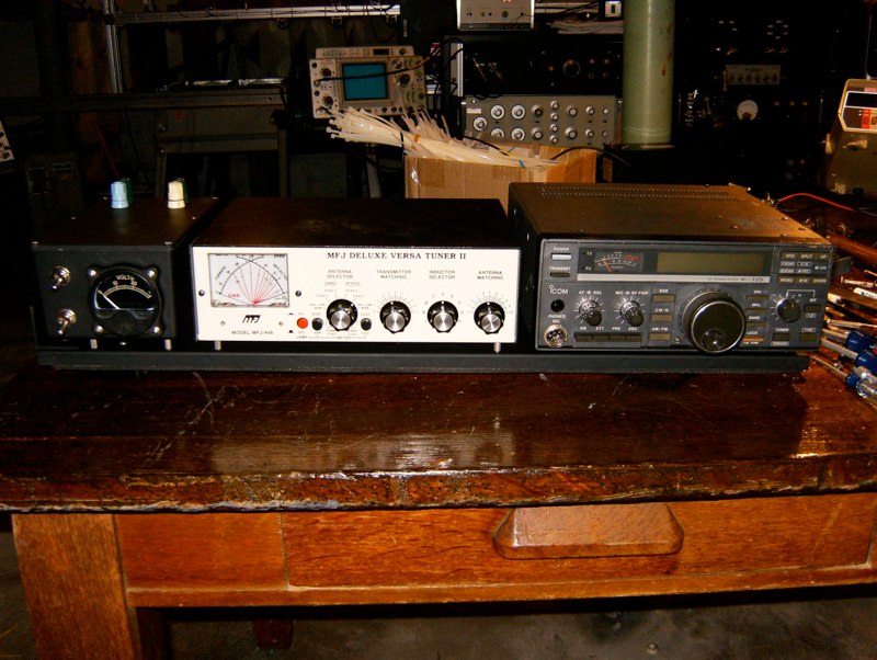
- Custom 12 VDC bus and voltage monitor
- 12 VDC 7.5 a/h lead acid battery pack
- External power
- 0.56-30 MHz receive, transmit on ham bands
- SSB, CW, AM
- PSK31 (plus RTTY and other modes) two-way radio station
- PSK31 interface box to laptop computer includes audio isolation transformers (to prevent RF feedback)
This system was developed as a fun alternative to setting up a permanent radio shack in my rental house.
Story
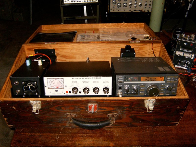
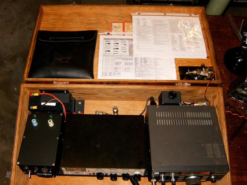
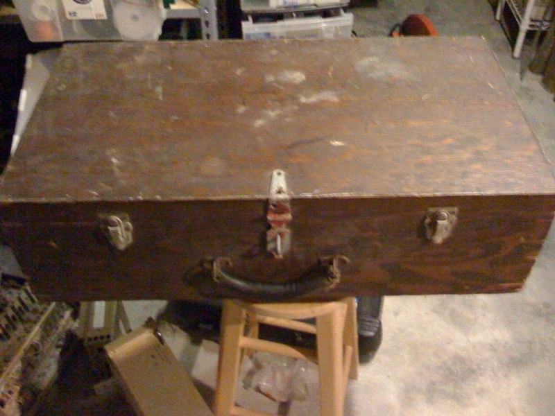
I have designed this station to be a portable with a compact, low-cost, powerful 100-watt HF transceiver; the Icom IC-725. I found a WW2 foot locker at a garage sale for $4 and thought that was the perfect form factor. When closed you can not tell that it is a complete radio station.
I had to design a method of mounting a small 100-watt HF radio, an antenna tuner, DC power distribution/metering into the WW2 foot locker while providing a good station layout for the operator. I also wanted to power it off of its own batteries or external DC. For this reason this station has a 7.5 A/h sealed led acid battery on-board with a toggle switch for selecting internal or external power. A second toggle switch will rout the battery terminals to two binding posts on top of the power distribution box so that a charger can be connected (or solar panels).
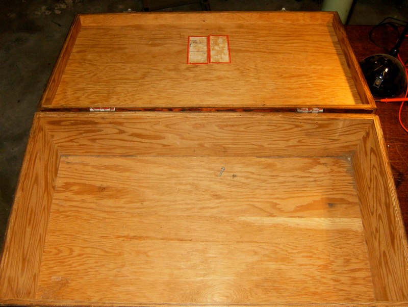
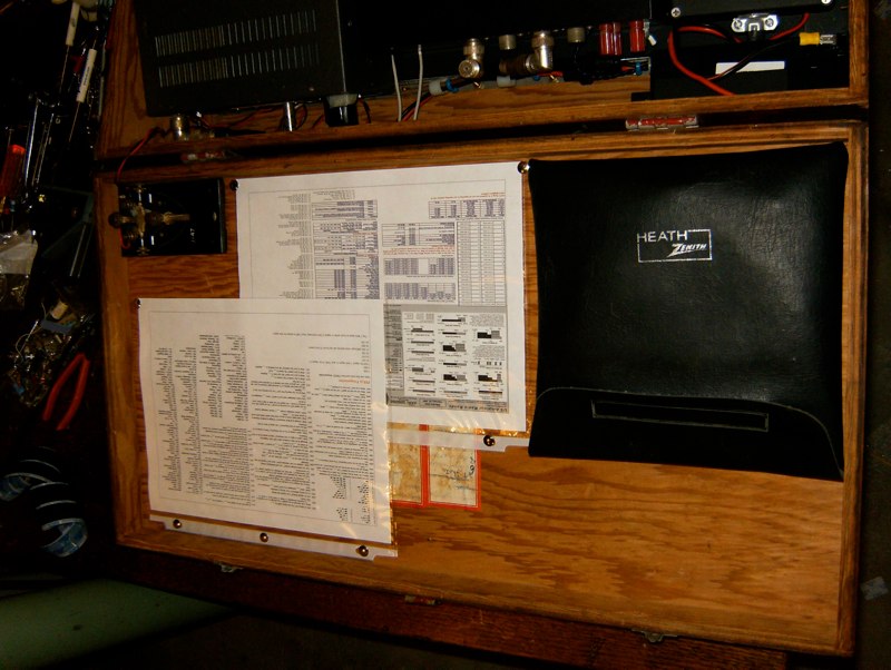
I cobbled together two quick-reference sheets that are tacked to the inside top-lid. These include all Q codes and other abbreviations that amateur radio operators use. These sheets also include a frequency list of the ham bands, short-wave bands, SSB ship-to-shore, and other interesting short-wave frequencies (see pdf’s below).
In addition to the quick reference sheets there is an old (circa WW2?) J-47 key and an old oscilloscope probe pouch that is used to store the dipole antenna, misc. cables and tools.
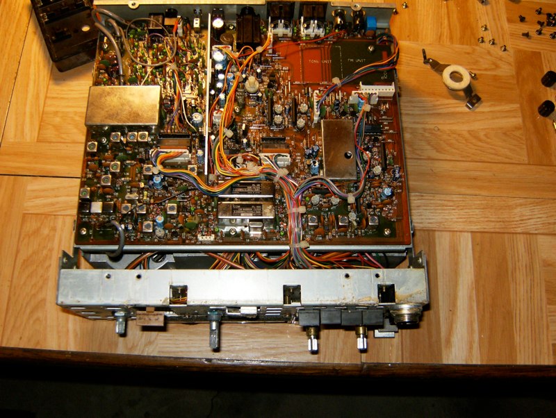
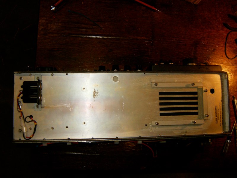
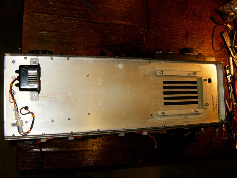
I purchased the IC-725 for $200. This radio was in working order except that it has a bad tuning encoder wheel. I purchased a replacement form Icom during the spring of 2009 for about $65. I had to completely disassemble the radio in order to replace the encoder. During re-assembly I found that the manual has a typo (see details below) with regard to where front panel wiring harnesses are to be plugged in.
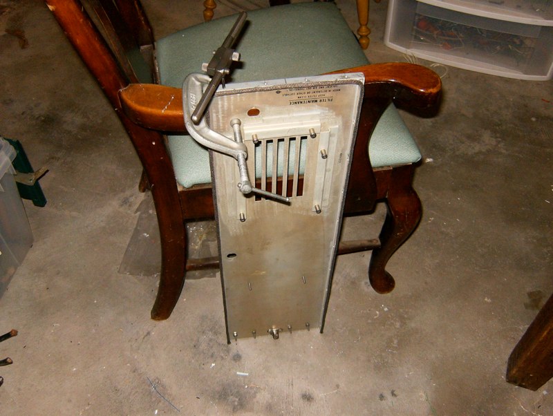
I wanted to securely mount the radio equipment and 12V power bus enclosure to the foot locker. The wood on the foot locker was old and very dry. I decided to use an aluminum frame for the dual-purpose of holding the radio equipment and to shore-up the foot locker. This was achieved by modifying an old aluminum door off of a military surplus microwave radio station. I painted it all black to look cool.
Once the station was wired up then mounted snugly in the foot locker I tested it out using a 65′ random wire connected to the ‘random wire’ binding post off of the antenna tuner and a second 65’ wire to the ‘ground’ binding post. The station was not connected to any sort of Earth ground because I believe finding or building an Earth ground is not desirable in a portable application. My goal was to operate without the use of an Earth ground.
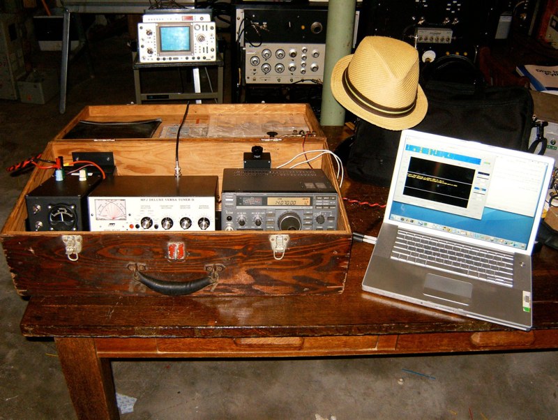
Using Cocoa Modem 2.0 on my Macbook laptop I attempted a PSK31 contact. My connections from the Macbook to the IC-725 were made by a direct cable to the rear AUX port of the radio. The lack of RF ground on a random wire antenna caused a minor RF burn on my hand while touching a corner of a metal surface connected to the radio equipment. It was clear that this antenna configuration was not going to work for portable operations.
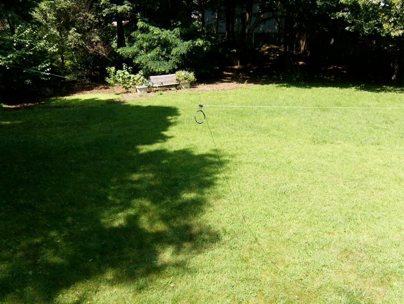
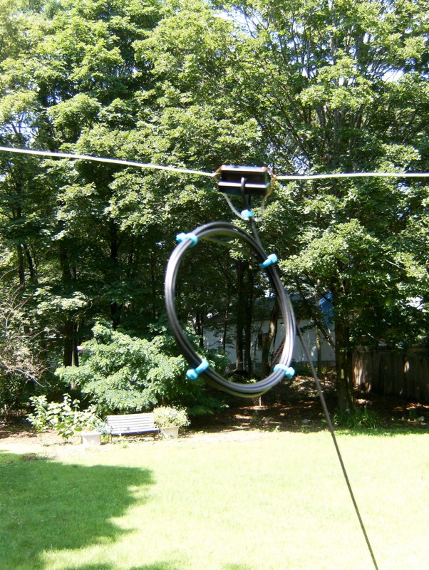
I then built up a half-wave dipole for the 20m amateur radio band, achieved a VSWR at 14.07 MHz < 1:6.
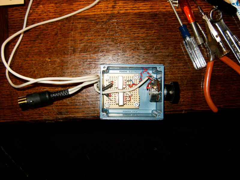
Tried making PSK31 contacts again and failed. It took me a week or more to realize that I was getting RF feedback through my computer sound ports. After searching online I realized that you want to use audio isolation transformers between the audio ports of your laptop and the HF rig, when you are transmitting a significant amount of power. For this reason I built a junction box with audio isolation transformers and a potentiometer for TX volume control (see engineering notes below). This box is actually located directly behind the IC-725 and bolted to the inside of the foot locker. This solved the feedback problem.
So I tried again. This time my very first contact was a UT2… call from the Ukraine! My next two contacts were from Cleavland OH, Norfolk VA, and Italy.
These first contacts were made using an external 20A supply. Next step is to try it on batteries only. I will post more the results of the battery test soon.
I encourage you to build your own PARTS. Send me pictures if you do!
73
Greg, N8ZRY
Portable Amateur Radio Two-way Station (PARTS) photos
Photos of the PARTS project. A complete HF radio station built into a WW2 foot locker.


Engineering Notes & Schematics
Manuals
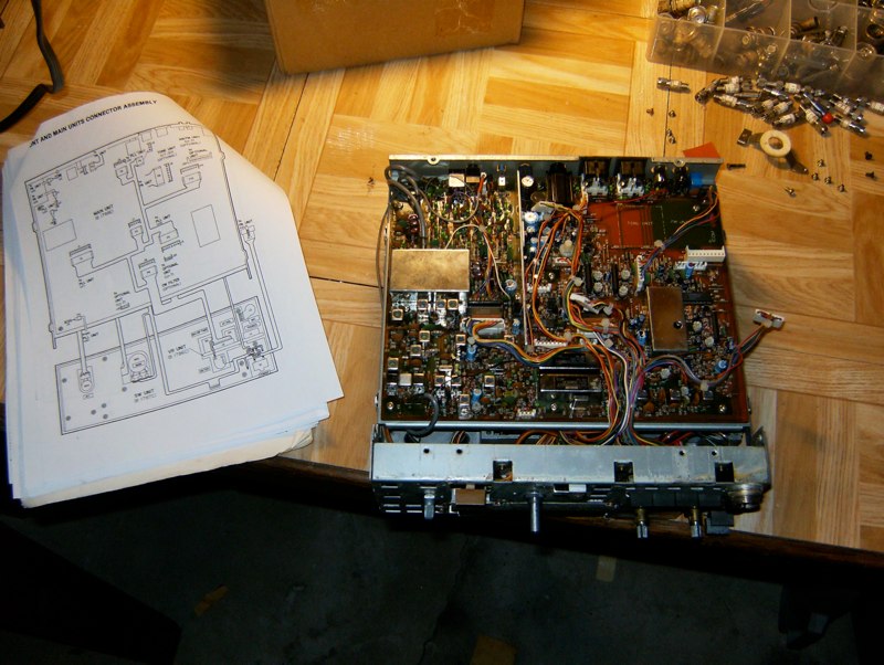
There is a typo in the IC-725 service manual shown here: IC-725 Service Manual. I found this typo while re-connecting the front panel to the two major radio boards inside of the rig. On page 5-3 P1 should be switched with P5. This is shown on page 7-4 where the schematic clearly shows where these cables should connect to.
Quick Reference Charts
These quick-reference charts were made by hastily pulling data off of numerous sites. I am not sure about the accuracy of most of the information presented here. The Q codes, ham abbreviations, and the ARRL frequency chart are accurate.
Quick reference chart: Q codes and other ham abbreviations.
Quick reference chart: Ham bands and other various short-wave frequencies.