S-band MIMO Phased Array Radar
UWB S-band MIMO Phased Array Radar System for Looking Through Dielectric Slabs
This system was developed as part of my Ph.D. dissertation at the Michigan State University Electromagnetics Research Group.
- 2-4 GHz UWB S-band chirp
- Utilizing airborne SAR imaging algorithm for beamforming
- Simultaneous transmit and receive (FMCW radar mode)
- 1 mW transmit power
- Range gate
- High sensitivity capable of imaging 1.25 inch tall nails
- Imaging through lossy dielectric slabs
Abstract
A near real-time radar-based imaging system is developed in this dissertation. This system uses the combination of a spatially diverse antenna array, a high sensitivity range-gated frequency-modulated continuous wave (FMCW) radar system, and an airborne synthetic aperture radar (SAR) imaging algorithm to produce near real-time high resolution imagery of what is behind a dielectric wall. This system is capable of detecting and providing accurate imagery of target scenes made up of objects as small as 6 inch tall metallic rods and cylinders behind a 4 inch thick dielectric slab. A study is conducted of through-dielectric slab imaging by the development of a 2D model of a dielectric slab and cylinder.
The SAR imaging algorithm is developed and tested on this model for a variety of simulated imaging scenarios and the results are then used to develop an unusually high sensitivity range-gated FMCW radar architecture. An S-band rail SAR imaging system is developed using this architecture and used to image through two different dielectric slabs as well as free-space. All results are in agreement with the simulations. It is found that free-space target scenes could be imaged using low transmit power, as low as 5 picowatts. From this result it was decided to develop an X-band front end which mounts directly on to the S-band rail SAR so that objects as small as groups of pushpins and aircraft models in free-space could be imaged. These results are compared to previous X-band direct conversion FMCW rail SAR work.
It was found that groups of pushpins and models could be imaged at transmit powers as low as 10 nanowatts. A spatially diverse S-band antenna array will be shown to be developed for use with the S-band radar; thereby providing the ability for near real-time SAR imaging of objects behind dielectric slabs with the same performance characteristics of the S-band rail SAR. The research presented in this dissertation will show that near real-time radar imaging through lossy-dielectric slabs is accomplished when using a highly sensitive radar system located at a stand-off range from the slab using a free-space SAR imaging algorithm.
Publications
- G. L. Charvat, L. C. Kempel, E. J. Rothwell, C. Coleman, and E. L. Mokole, ``A through-dielectric ultrawideband (UWB) switched-antenna-array radar imaging system" IEEE Transactions on Antennas and Propagation, Vol. 60, No. 11, November 2012, pp. 5495-5500.
- G. L. Charvat, L. C. Kempel, E. J. Rothwell, C. Coleman, E. J. Mokole. "An ultrawideband (UWB) switched-antenna-array radar imaging system" Waltham, MA: IEEE International Symposium on Phased Array Systems & Technology, October 2010.
- Slides from this Conference
- G. L Charvat, L. C. Kempel, E. J. Rothwell, C. Coleman, “A Low-Power, Real-Time, S-Band Radar Imaging System.” Boston Massachusetts: Antenna Measurement and Techniques Association Conference, November 2008.
- Slides from this Conference
- G. L. Charvat, “A low-power radar imaging system,” The Boston Chapter of the IEEE APS Society, December 11, 2007
- G. L. Charvat, ``A Low-Power Radar Imaging System," Ph.D. dissertation, Dept. of Electrical and Computer Engineering, Michigan State University, East Lansing, MI, 2007.
Engineering Notes
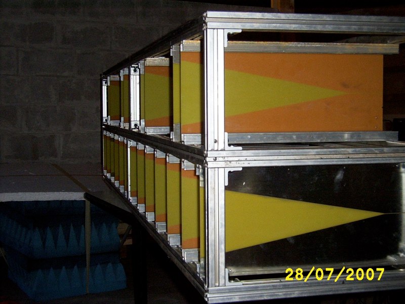
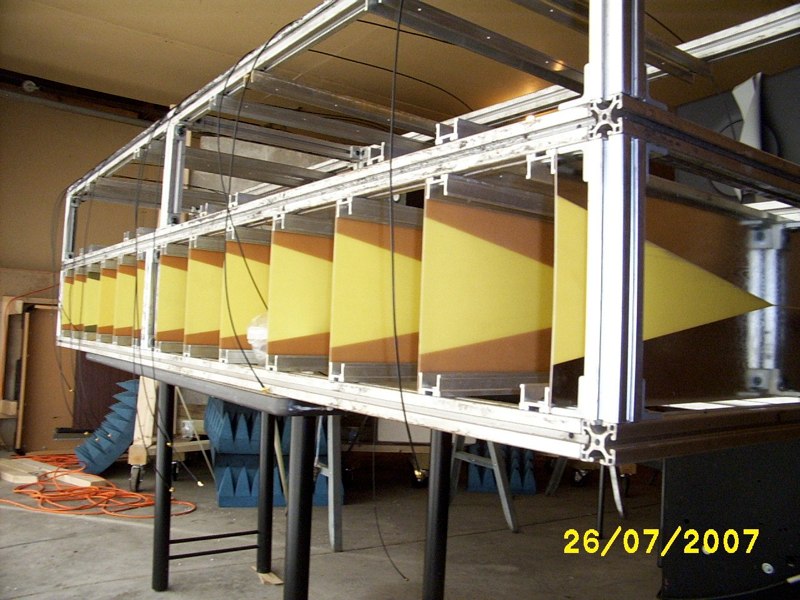
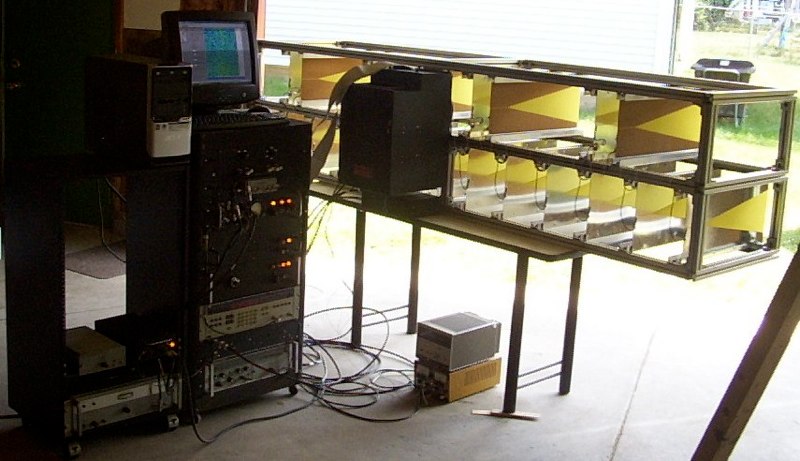
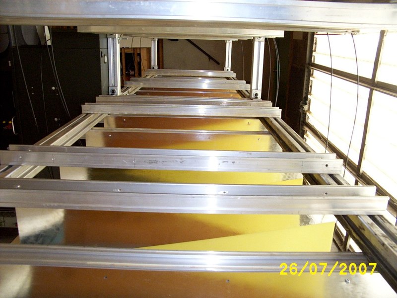
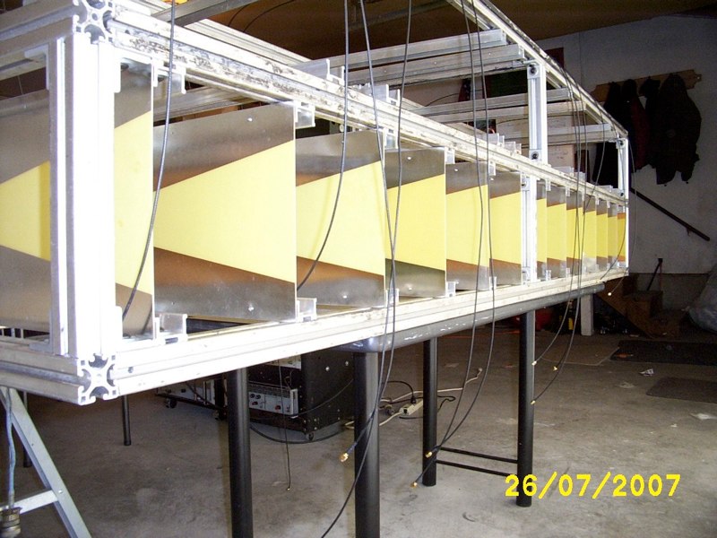
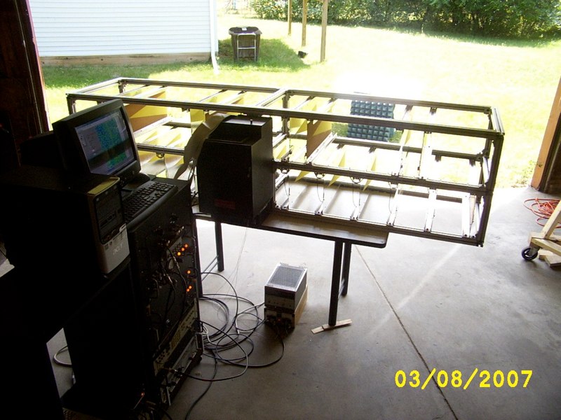
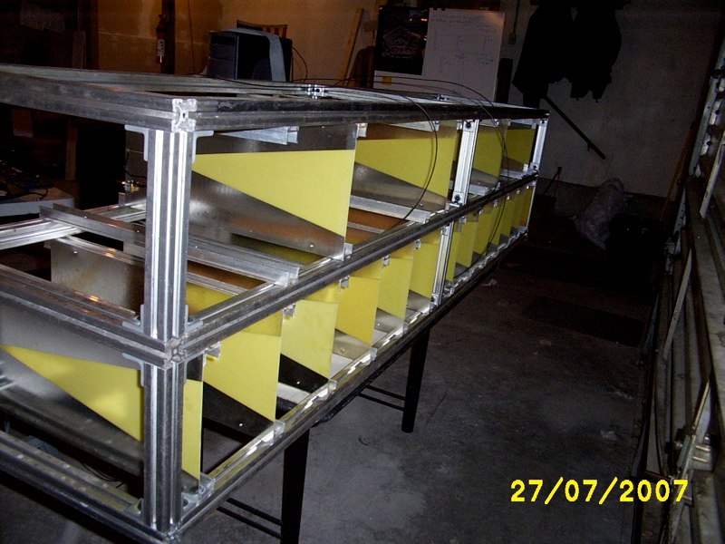
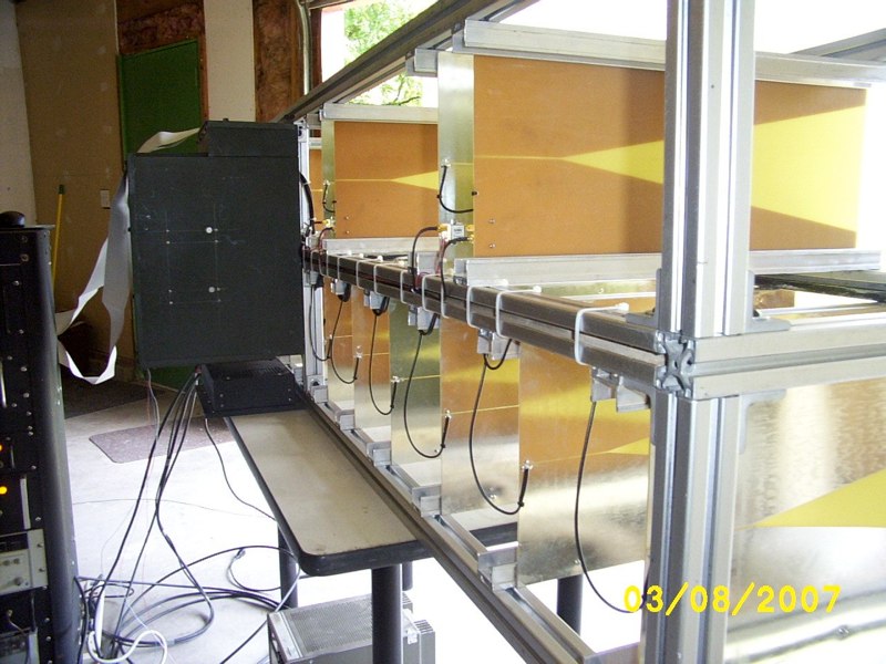
The Real-Time S-Band Through-Slab Antenna Array SAR Imaging System Hardware
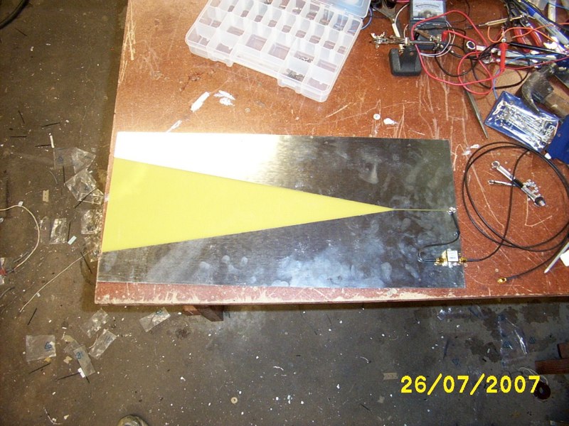
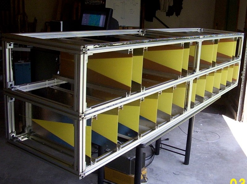
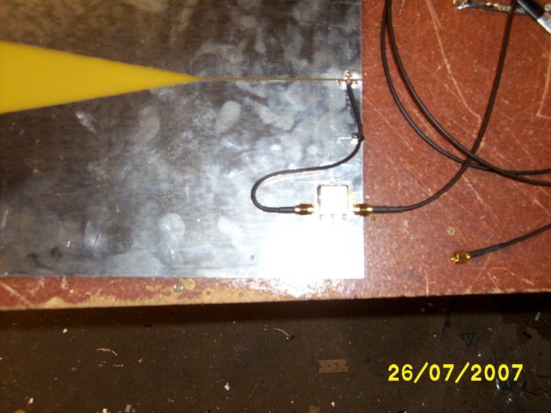
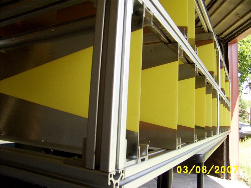
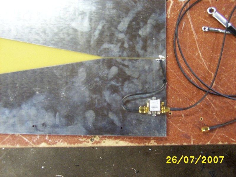
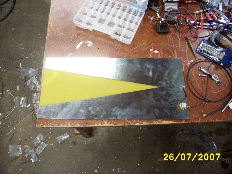
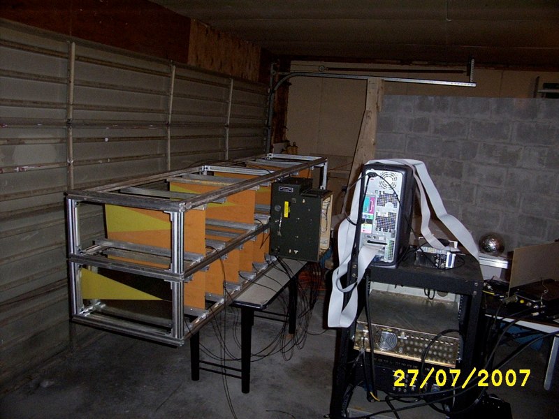
It is difficult to describe this part of the dissertation in so few words. This is a real-time through-slab SAR imaging system, which produces a SAR image on a computer screen in real-time. It is basically a radar video camera which can see through dielectric slabs (or you can SAR image things in real-time in free space, you decide). You can image moving or stationary targets. This radar operates at stand-off ranges, approximately 20’, or more if need be. The transmit power is 1 milli-watt. The large antenna array shown connects to a switch matrix. The switch matrix connects the S-band rail SAR front ends to the array. More info is available if you look at the pdfs.
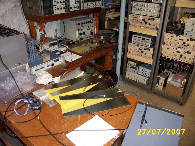
Most of the pictures shown here are of the array at various times during its construction.
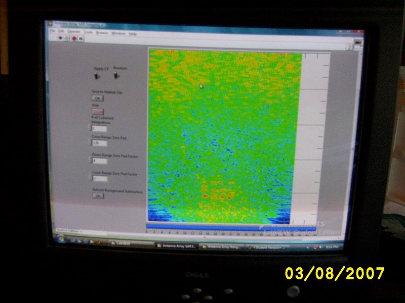

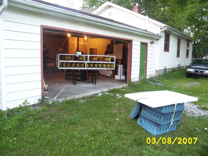


The Real-Time S-Band Through-Slab Antenna Array SAR Imaging System Imagery
Shown here is data from the real-time through-slab imaging S-band radar system. Two experiments are shown; free space and behind a lossy dielectric slab. In both cases transmit power was 1 milli-watt. When imaging targets behind a slab the radar was located 20 feet from the slab and targets were approximately 10 feet behind the slab. A video camera was placed on a tripod in front of the radar system (hence the low quality of video shown here). Shown in the pictures below are the experimental setups and some of the hardware.
All data shown here was acquired at MSU in the summer of ’07.


